Geometries Details
Geometry Details
In the Geometry section of the left part of the mask
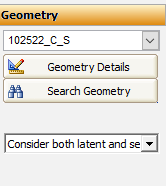
to see the details of the selected geometry (in this example the 102522_C_S) → Geometry Details:
Where
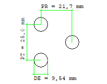
- “DE” stands for “External Diameter” of the coil
- “PT” stands for “Rows Spacing” of the coil
- “PR” stands for “Tubes Spacing” of the coil
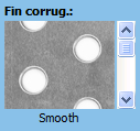
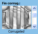
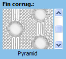
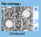
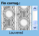
The following Fin corrugation types are available:
- “Smooth” Fin
- “Corrugated” Fin
- “Pyramid” Fin
- “Windowed” Fin
- “Louvered” Fin
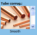
The following Tube corrugation types are available:
- “Smooth” Tube
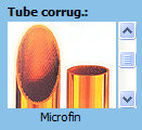
- “Microfin” Tube
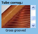
- “Gross Grooved” Tube
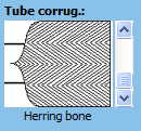
- “Hearing Bone” Tube
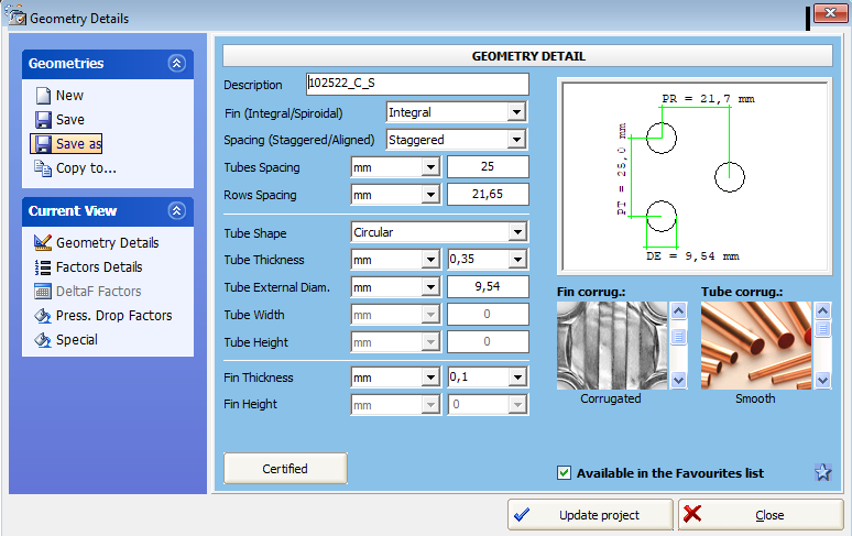
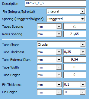
We can also see the Description and other geometry detailes:
where
- “Description” is a string that identifies a geometry
- the first two digits “10” stand the tube external diameter rounded
- the third and fourth digits “25” stand for the Tubes Spacing
- the fifth and the sixth digits “22” stand for the Rows Spacing rounded
- the last two characters stand for the initial of Fin and Tube corrugation Type
The user can change the name of the geometry at his discretion.
- “Fin” can be Integral or Spiroidal

- “Spacing” can be Staggered or Aligned

- “Tube Spacing”
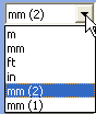
 can be defined in
- “Fin Spacing”
 can be entered in
 .
.
The other parameters we can set or see are:
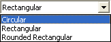
- Tube Shape
 which can be
- Tubes Thickness

- Tube External Diameter
 if the tubes are circular
- Tube Width
 and Tube Height
  if the tubes are rectangular
- Fin Thickness

- Fin Height

There is another area we can see:
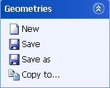
 permits to add a new geometry.
 permits only saving by default
 permits to give a file name while saving the geometry
 permits to copy a geometry from one treatment to the other
** For further information about the geometries factors and theirs possible values, please see section “Geometry management” **