Heating example

Heating Example
To open an example of Heating calculation modality, click twice on “Heating.c6prj” file under the “recent projects”

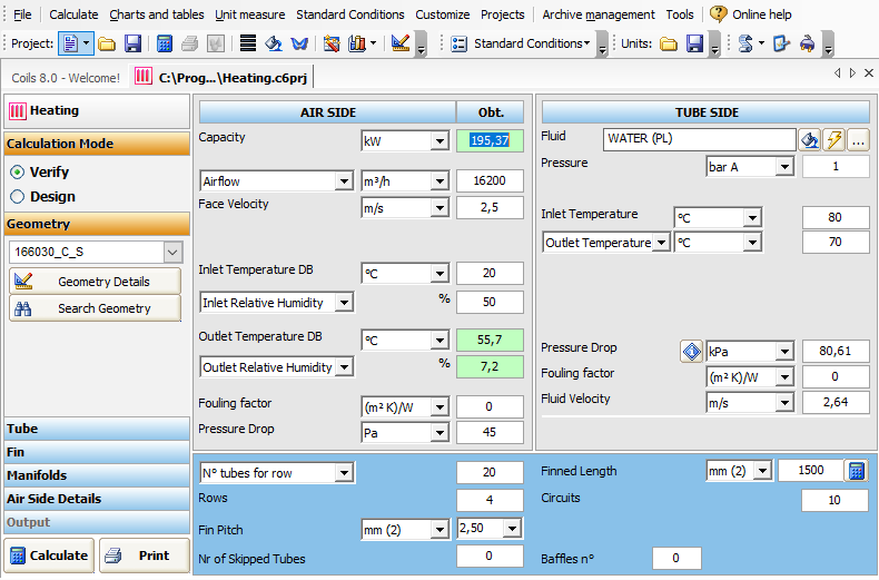
Where we can see four main areas.
- Calculation type and relative Geometry, Tube data, Fin data, Manifolds Data, and Air Side details
- AIR SIDE data with relative parameters.
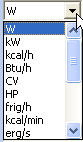
- “Capacity” measured in W or it can be measured in
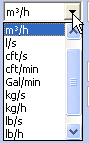
- “AirFlow” measured in m3/h but can also be set in
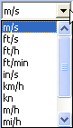
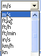
- “Face Velocity” measured in m/s but can also be changed in
- “Inlet Temperature DB” measured in °C but can be changed

- “Outlet Temperature DB” measured in °C but can be changed

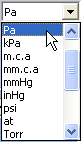
- “Pressure Drop” measured in Pa or in
- TUBE SIDE data
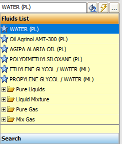
- “Fluid” - in this example we use WATER, but we can use a wide range of fluids
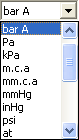
- “Pressure” measured in bar A or in
- “Inlet Temperature” measured in °C or in °F
- “Outlet Temperature” measured in C or in °F
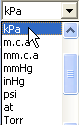
- “Pressure Drop” measured in kPa or in
- “Fluid Velocity” measured in m/s or in
- Coil Data
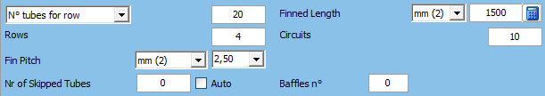
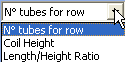
- “N tubes for row” or it can be expressed in
- Rows
- “Fin Pitch” measured in mm or in “in”
- “Nr of skipped Tubes” which is the number of not alimented circuits
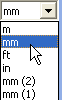
- “Finned Length” measured in mm or in
- “Circuits” which indicates the number of circuits
- “Baffles n°” which indicates the number of the baffles.
As indicated in the introduction, the software is able to perform two calculation modes “Verify” and “Design”.
Since in this example we have all the working conditions, we work in Verify mode, in which the user can rate the capacity and the pressure drops knowing all the geometrical parameters of the exchanger and the working conditions, changing one or more input variables at the same time (for example: geometry, inlet air temperature and humidity, fluid, fin thickness, fin type, tube type, fluid temperatures etc.)
In Calculation area we can see that we are working in the “Verify modality”, which is selected .
Now we can calculate the project 
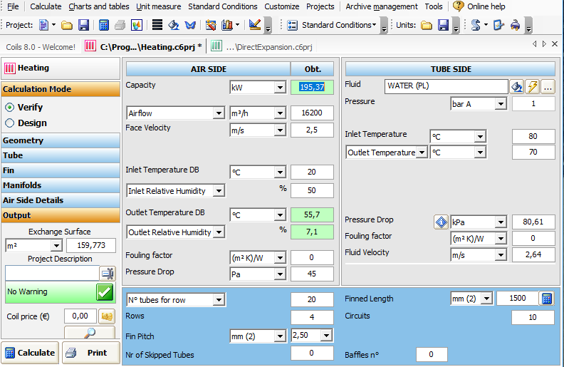
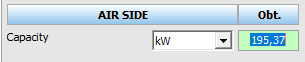
where the Capacity is calculated and indicated on the AIR SIDE
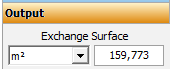
the exchange surface is indicated in OUTPUT DATA on the left side of the main window
the “No Warning ” message indicates that the working conditions were correct.

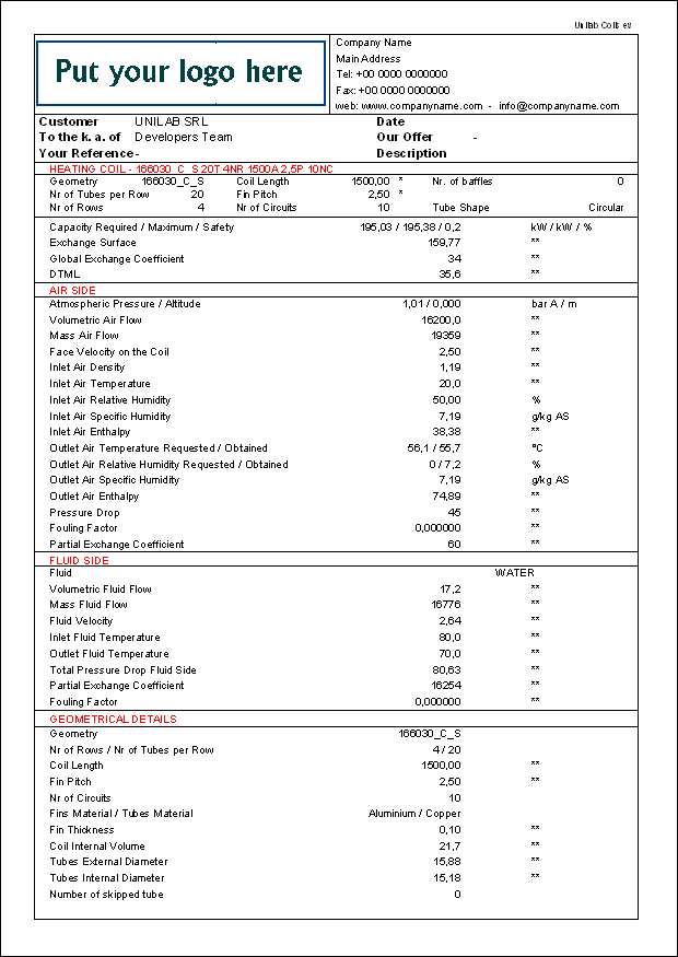
to see the calculation results, press the “Print” button 
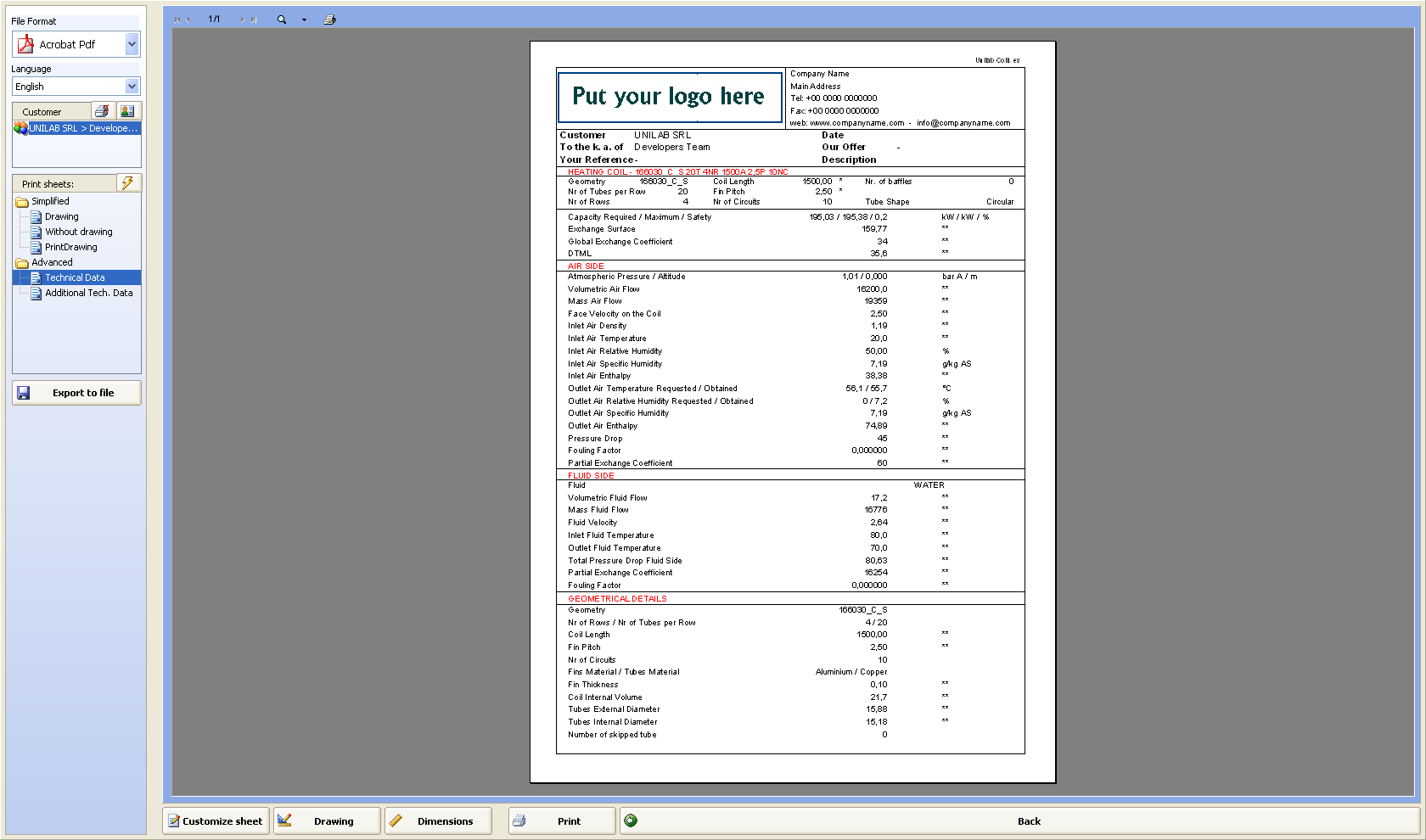
Where we have:
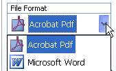
- “File Format” where by clicking on its menu, we can choose between Pdf-format or Word-format
- Language (the report is available in 15 languages)
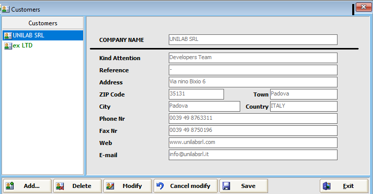
- “Customer” where we can add the customer data, that will be used in printouts
- “Printout templates” which allows to see detailed pages before to stamp.
For example, if we choose the Simplified Drawing , will obtain
by choosing the “Without Drawing” option:
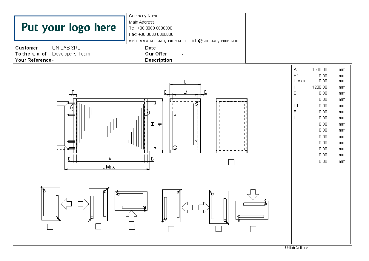
by clicking “PrintDrawing” option:
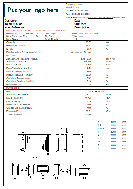
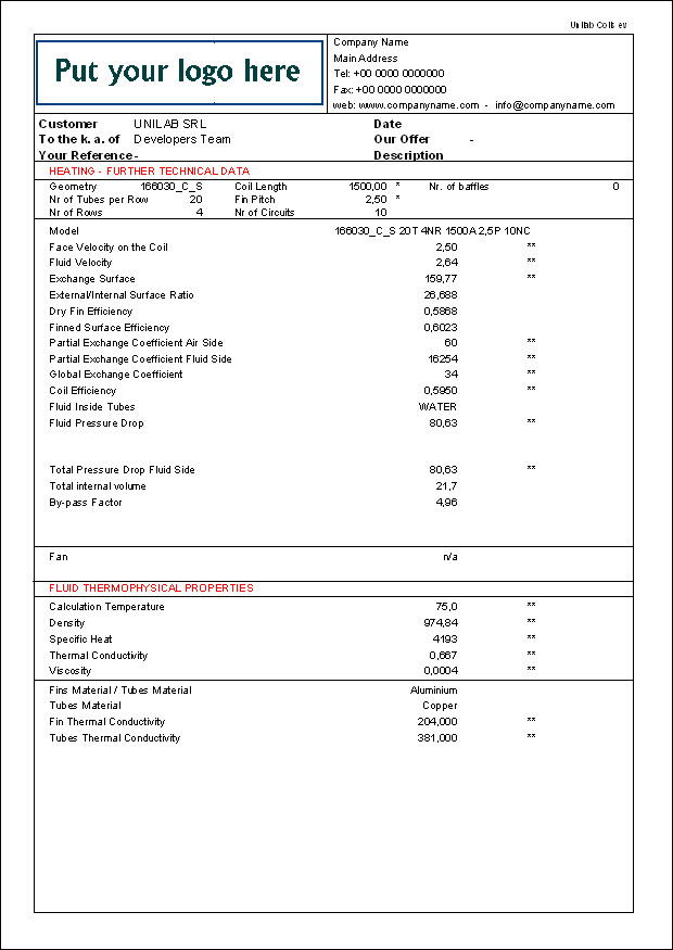
the “Advanced Technical Data” :
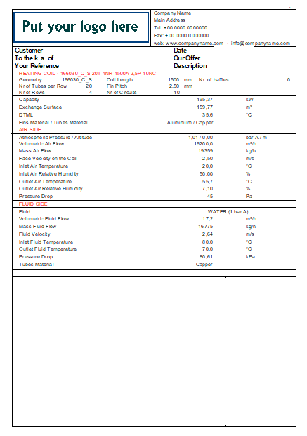
the “Advanced Additional Technical Data”:
Let’s see, how the Design modality works.
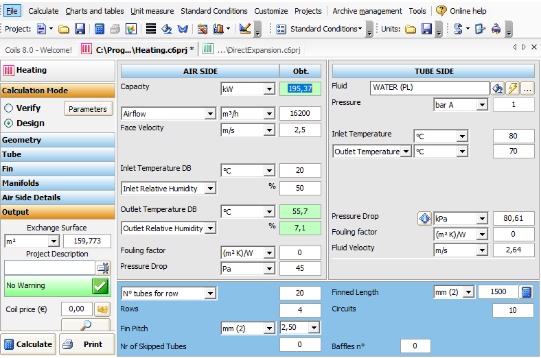
where on “Air Side” we can see “Pressure Drop ” measured in Pa, as calculation’s result.

in the “Tubes Side” We can see “Pressure Drop” measured in kPa, as calculation’s result.

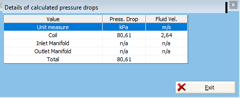
Clicking on “i” we can see an information about calculated pressure drop
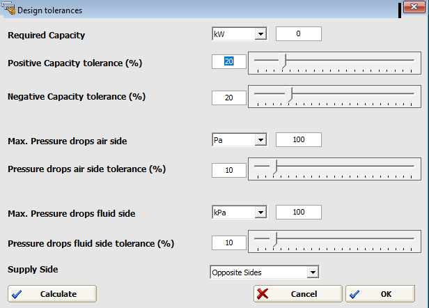
Choosing the “Design” mode and obtain the following, where you should set the tolerances and the required capacity
We click on “Calculate” button 
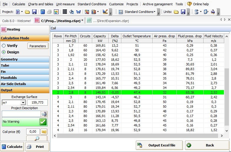
where we can see a list of all possible coils chosen by software and based on the requested Capacity value:
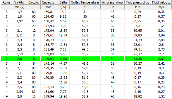
In this table we can see some fields relative to the coils geometries
Delta (%) stands for the percentage difference from the capacity we are seeking.
the remaining fields are about the air and fluid side variables

The highlighted row shows chosen coil, that fits best the capacity sought.
